Building an electromagnetic treasure chest with JavaScript
Learn hardward from a software background
As part of a murder mystery party, I built a escape room-like locked treasure chest, that players opened by entering a code into a web interface. We recently gave a talk with an overview of the whole project, but had to cut some details I learned about how electronic circuits work and how you can determine parts needed for your own projects. Let’s dive back in with the uncut notes!
Architecture
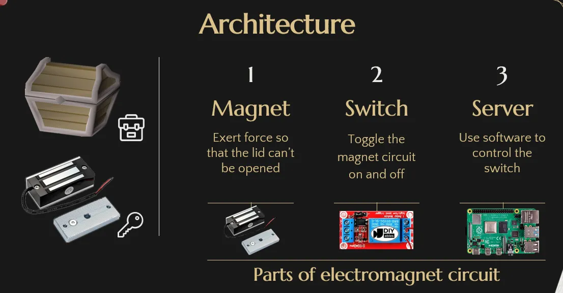
There are 3 components to the treasure chest lock. All of them are connected to each other in a single unit called the “electromagnetic circuit”.
- The magnet holds the lid shut
- The switch turns the magnet circuit on and off
- The server controls the switch programmatically
Magnet
The lock works by holding down the lid of the treasure chest using a magnet.
The body of the chest has the magnet attached. It’s an electromagnet, aka a magnet you can turn on and off with electricity.
Attached to the lid is a metal bar that will get stuck to the magnet when it’s turned on. The bar has a little button so that once the magnet turns off, the button pushes away the metal bar a little so they’re not stuck together.
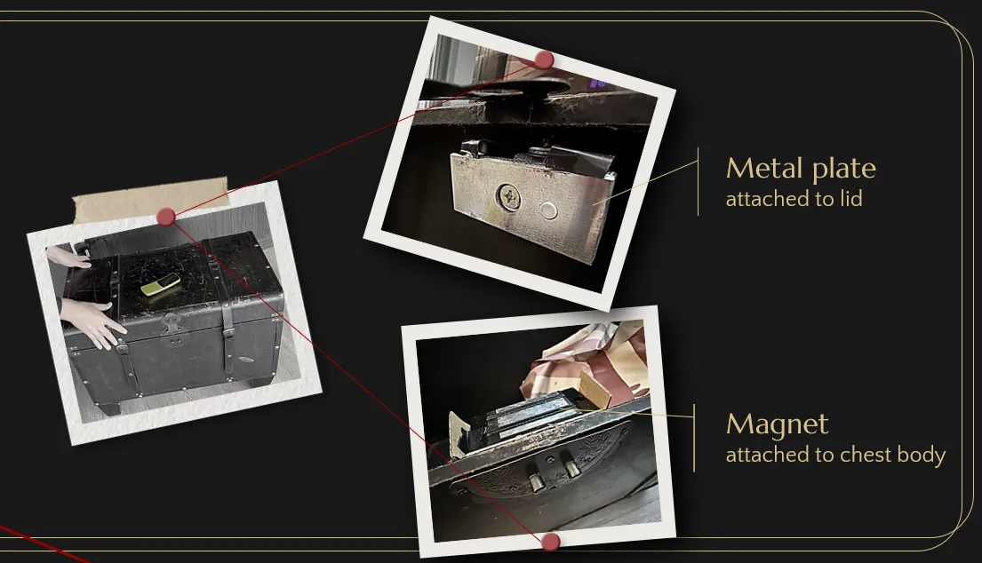
It was a bit of a challenge to attach the metal bar to the lid since it’s hole is parallel to the magnet. We ended up using an L shaped bracket with screw holes from the hardware store, but it was a bit janky as it doesn’t line up perfectly. Next time we should 3d print the bracket.
Light switch metaphor
In the following sections, we will be going over circuit on a conceptual level so can make your own modifications and know what parts to buy.
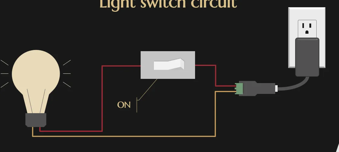
To illustrate how our circuit works, let’s look at a light bulb. In this diagram, we have a light bulb, an on-off switch, and a power supply. The circuit is basically one big circle that can be severed when the switch is off, but when the switch on, the current flows and the light is now shining bright like a diamond!
Voltage levels
The most important number that matters when buying parts is the Voltage, which measures the electric potential.
In this example, the bulb requires 12 volts, and the power supply also outputs 12 volts. The voltage must match between the light bulb and power supply.
The purpose of that big gray brick plugged into the wall is to convert power from the wall, which is 230V in UK/100V in Japan, to the amount we want
you don’t need to worry about voltages when buying the light switch, as the light switch is just a wire you can open or close. The same wire can support different voltages flowing through.
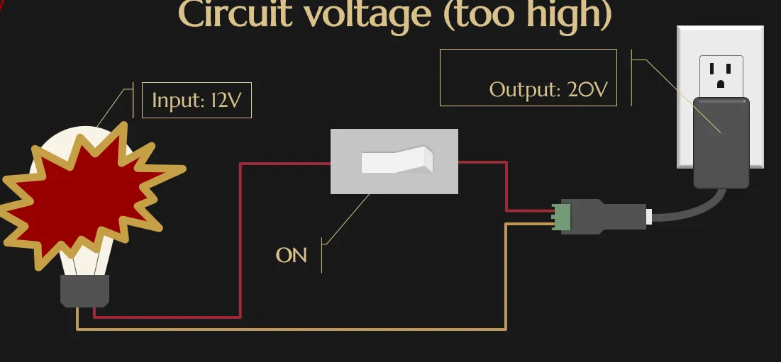
(Make this an interactive sample where you can adjust voltage level)
If the voltage from the power supply is lower than what the light bulb needs, then the bulb will be dim, If the voltage is higher than what the light bulb uses, then the light bulb will burn out.
Electromagnet instead of bulb
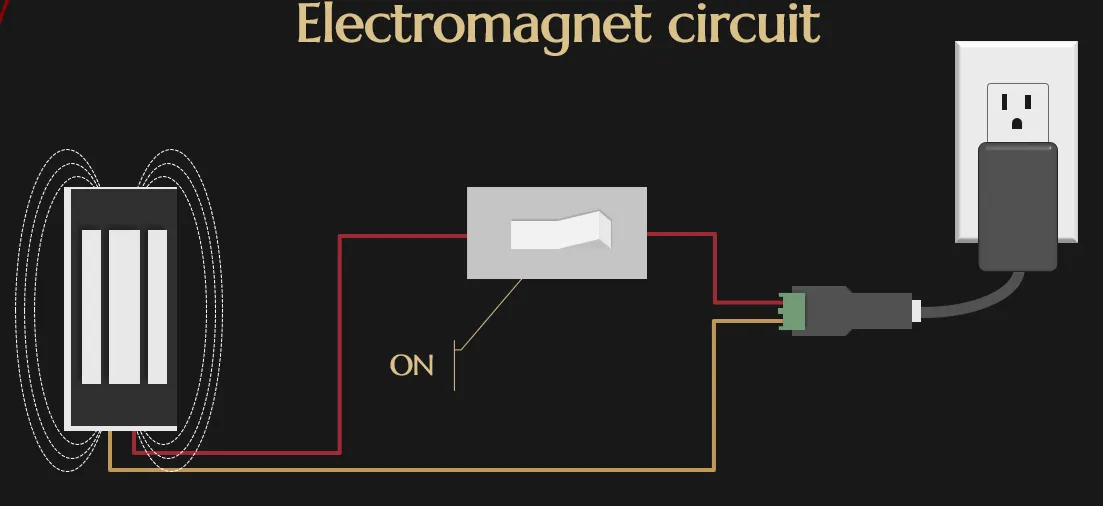
Our electromagnet circuit works the same way as the light bulb circuit. When the electromagnet is powered, instead of emitting light, it produces a magnetic field, and this would hold down the metal plate attached to the lid so the treasure chest cannot be opened.
And just like the light bulb, the voltages on both sides must match up.
Switch
Let’s talk about the light switch. In a house, a switch is something that can flip off and on with your index finger (or your middle finger if you’re having a bad day). The equivalent to that in our circuit is something programmable called a “relay”.
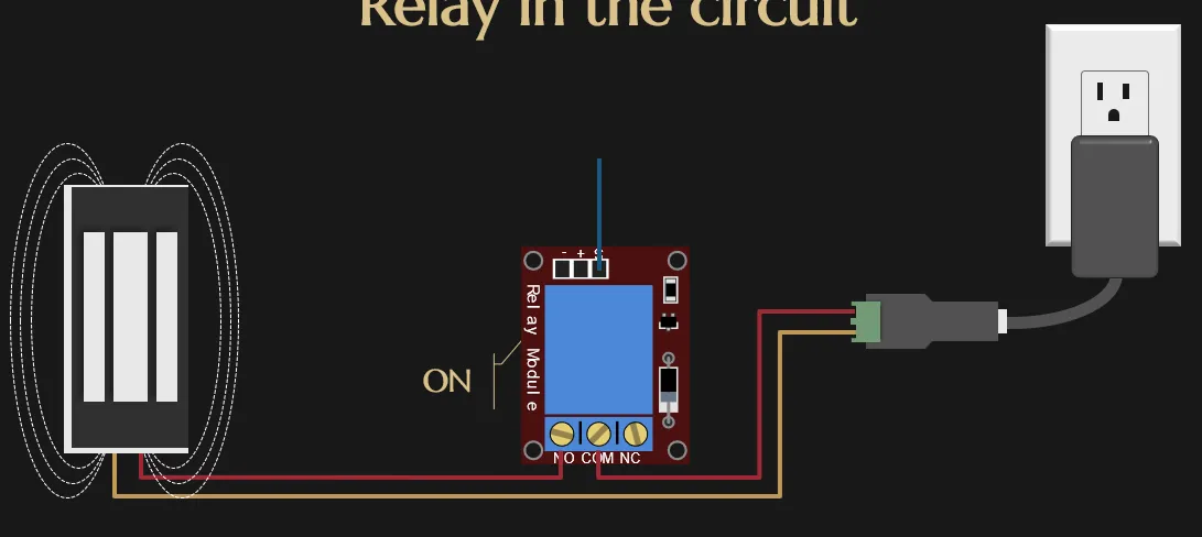
Just like the light switch, the relay is inserted into the middle of the circuit.
You plug wires into the ports labelled “N.O.” and “COM”, at the bottom of the relay
You can programmatically toggle it on using a “signal wire” (that’s blue in our diagram), which is inserted into a port usually labelled “S” or “IN”.
Just like a switch, the relay allows any voltage to be passed through.
However, it does consumes 5 volts of power from an second power supply (aka the second outlet). This does not impact the elctromagnet.

Switch === Relay
Finger === Signal wire
Server
So let’s talk about how we can start controlling this relay using a server. We’re going to connect this relay to a Raspberry Pi.
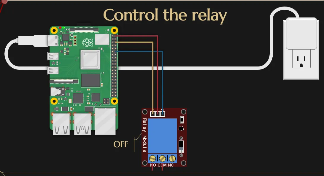
The Raspberry Pi is just a simple computer that runs Ubuntu and has pins to plug wires into.
So here we take the signal wire and just plug it into an arbitrary port on the Raspberry Pi.
We’re also going to connect a red wire into the positive pin and a yellow wire into the negative pin, so that we can supply power to the relay.
By the way, none of the wire colors matters since they’re are just metal with insulation around it. You can any color…or all the same color for that matter, if you enjoy a good puzzle!
If you look up electronic kits online most will tell you to use an Arduino instead of a Raspberry Pi. The Raspberry Pi is a full on computer running an operating system, whereas Arduino doesn’t include an operating system and just runs the bare minimum amount of code needed. As a result, it’s usually faster. However, the Raspberry Pi is much closer to the computers we develop on day to day so it’s easier to work with when you come from a web development background.
Raspberry Pi pin header
The Raspberry Pi’s pins do different things.
The only thing that really matters is that there’s:
- a group of pins that supply power (where the positive wire goes),
- a group of pins that are the ground (where the negative wire goes),
- and then finally there are GPIO pins (aka General Purpose Input Output pins), which can each be programmatically turned on and off using software in Ubuntu or Node.js.
It doesn’t really matter which pin in these pools that you’re picking. I just picked out the highlighted ones arbitrarily. You just need to pick one from the power pool, one from the ground pool, and one from the GPIO pool.
Server software
The pin we picked is labeled as GPIO 18, so we can control it by using the same ID in software.
So, using the on off library on npm, we get an interface to read and write to the pin, which eventually controls the magnet.
import { Gpio } from 'onoff';
// Control GPIO pin 18const magnetRelay = new Gpio(18, 'out');
// Turn signal on, which connects magnet circutawait magnetRelay.write(1);
// Turn signal off, which breaks magnet circutawait magnetRelay.write(0);
If you write 1, it’ll turn it on. If you write 0, it’ll turn it off.
We can then connect this to an HTTP server. We’ll create a server where whenever we get a POST request, we’ll check what the current state of the signal pin is and then toggle it to be the opposite.
import { Gpio } from 'onoff';const magnetRelay = new Gpio(18, 'out');
async function onRequest(request: Request): Response {  const signalOn = (await magnetRelay.read()) === 1;  switch (request.method) {    case 'GET':      return Response.json(signalOn);    case 'POST':      await magnetRelay.write(signalOn ? 0 : 1);      return Response.json(!signalOn);  }}
The server can also handle a GET request and it’ll just return the current state of the pin.
Now that we have this, if we send a POST request to our new server, what will happen is that it will turn the pin on, which turns the signal wire on, which controls the relay, which controls the electromagnet, which unlocks the treasure chest! (make each part progressive bigger text size)
The complete circuit
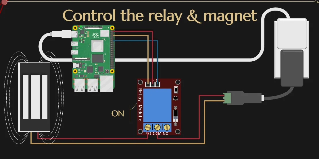
Going back to this circuit as a whole, we now have these two circles:
- the bottom circle is between the electromagnet and the power supply
- the top circle is between the relay and the Raspberry Pi.
And these two circles are the entirety of our circuit! Check out our talk to see how to incorporate an password entry website with the lock and connect it to a bigger event.